
Technical support
-
- General
- IP Camera Compatible List for WG DVR(NVR)
IP Camera Compatible List for WG DVR(NVR)
PDF Download * Support free IPC integration (Need to send IPC sample to WEBGATE)
-
- General
- HDD Compatible List for WG DVR/NVR
-
- IPC
- IP camera network configuration tool
Use the IP Tool to adjust IP camera addresses to match your network environment during setup.
※ For models not listed in the table below, please download the software from the specific product page or contact us at +82-1644-3421 for assistance..
Name/Version Supported Models Resources IPTool_v3.x.x NK2200 series, WNK-210 series, TTA-20 series
NE2106 series, WNE-210 series
NK5100 series, TTA-50 series
NE5106 series, WNE-510 series
Flame Detection Camera(Excluding NK1080 series)
IPTool_v2.x.x NK1080 series
NE2100 series, NE5100 series
NM2100PT-IR-Z23, NM5100PT-IR-Z30
NT2000BL-ANPR-F722
NT1080 series, NT2100 series, NT4100 series
NT5000 series, NT5100 series
Flame Detection Camera(NK1080, Flame series)Download -
- General
- How to upgrade DVR(NVR) firmware through network
How to upgrade DVR(NVR) firmware through network PDF Download Network Upgrader (Version 2.2.2) Download Local network upgrade
1) Run Network Upgrader program.
2) Select the firmware (ex. edvr_xxxx_xxxx.dat) to be used.
3) Select the DVR(NVR) to be upgraded from the list and enter Admin Password of DVR(NVR).
4) Click Upgrade button.
5) DVR(NVR) will reboot after finish the upgrade.External network upgrade
1) Run Network Upgrader program.
2) Select the firmware (ex. edvr_xxxx_xxxx.dat) to be used.
3) Click “Add a model directly” button, enter IP address & port number.
4) Click “Add model” button.
5) Select added DVR(NVR) from the list and enter Admin Password.
6) Click Upgrade button.
7) DVR(NVR) will reboot after finish the upgrade. -
- DVR
- Video Input(BNC) Guide -UHD series
Video Input(BNC) Guide

-
- DVR
- TDM Input Guide -UHD series
TDM Input Guide
Model Input
ChannelMultiplexed
channel numberAllocated channels Remarks UHD1604F-U Even
ChannelTDM(2~8CH) Channels will be allocated from
input channel to below channels up to multiplexed numberUHD1604F-U only UHD1608F-P Odd
ChannelTDM(2~8CH) Channels will be allocated from
next channel to below channels up to multiplexed numberUHD1608F-P only Ex. TDM Input

TDM Allocated channels table

-
- SW
- [DVR Quick Guide] Installation manual -Register for PC/Mobile monitoring
-
- General
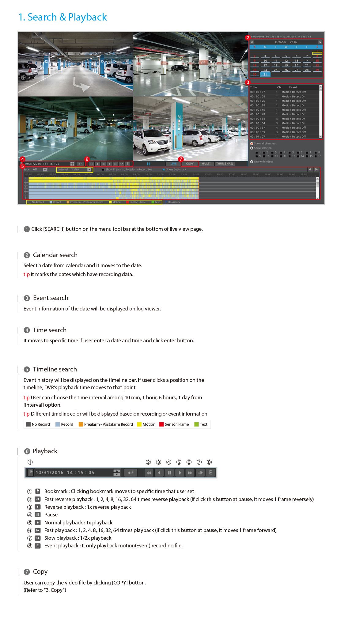
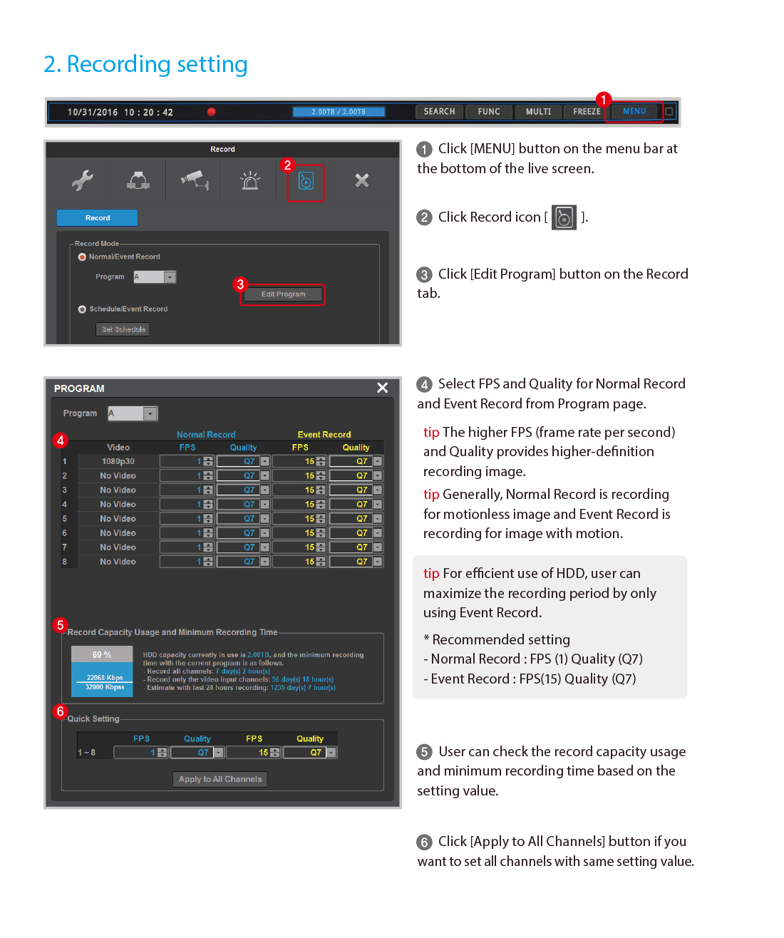
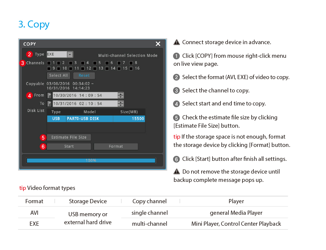
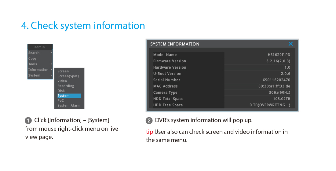
- [DVR Quick Guide] User manual -How to use major features of DVR
-
- General
- How to upgrade Firmware
How to upgrade Firmware - PDF Download Case 1. On normal condition(Normal booting state) -For all version
1) Unzip the firmware file(zip file) downloaded.
2) Format USB memory that you are going to use for upgrade to[FAT32]form at PC.
3) Copy edvr_xxxx_xxxx.dat file out of three(.dat/ .exe / .png) to USB memory.
tip. Make sure copy only Firmware file(.dat) but the entire folder. or DVR(NVR) cannot lead the file within a folder.
4) Connect USB memory with USB port in front of DVR(NVR), then upgrade screen pops up.
5) Press [YES] on the popup screen so that upgrade starts on. Once upgrade is done, DVR(NVR) automatically reboots with beep sound.
tip. If upgrade fails. check model name written on firmware and on DVR(NVR). upgrade will not progress when model names aremutually different.
6) Check firmware version to see if upgreade done well by clicking [Menu –System –Utility –System Information]
Case 2. On abnormal condition(Stop booting, “Please Wait..” state) –For version 8.2.16 and higher
1) Unzip the firmware file(zip file) downloaded.
2) Format USB memory that you are going to use for upgrade to[FAT32]form at PC.
3) Copy edvr_xxxx_xxxx.dat file out of three(.dat/ .exe / .png) to USB memory.
tip. Make sure copy only Firmware file(.dat) but the entire folder. or DVR(NVR) cannot lead the file within a folder.
4) Connect USB memory with USB port in front of DVR(NVR) and reboot DVR(NVR) power.
5) When progress bar is 100% full, DVR(NVR) will reboot, showing “now rebooting” message on the screen. Remove USB memory form DVR(NVR) then.
6) Check firmware version to see if upgreade done well by clicking [Menu –System –Utility –System Information]
-
- General
- Batch update DVR’s channel name
- Easily change each channels’ name by using USB memory
- Effective management and minimize DVR setting time(How to apply)
1. Make text file (*.txt) using PC and describe name of each channels in the following format (Can skip channels not change name)
2. Save the text file name as “wgi_channel_name.txt” and select the letters encoding as “UTF-8”
3. Copy the “wgi_channel_name.txt” to USB memory and insert it to DVR.
4. After beep sound, channel names will be automatically changed within 5 seconds.
-
- General
- Apply Booting Logo and Empty Channel Logo
- User can change the logo image for booting screen and empty channel
- User can apply customized logo for advertisement or customer service as necessary(How to apply)
1-1. Booting screen : Copy image file with the name of “wgi_boot_logo.jpg” to USB memory (720×480, jpg file format, less than 512KB / FAT32 USB format)
1-2. Empty channel : Copy image file with the name of “wgi_app_logo.png” to USB memory (png file format, less than 512KB / FAT32 USB format)2. Insert USB memory to DVR and reboot after beep sound, Image will be applied after rebooting

-
- Camera
- Video output format setting (Control with OSD button)
User can select video output format among HD-SDI, EX-SDI and EX-SDI2.0

-
- General
- Utilization of Fiber Optic Converter
Increase transmission distance of HD-SDI signal by using Fiber Optic Converters
The transmission distance of HD-SDI is about 200m based on 5C-HFBT cable. The transmission distance can be maximized by using fiber optic converters with easy installation.
The fiber optic converter & cable support maximum 20Km transmission of Full-HD image and camera control command.
Transmission distance table by coax cable types
The transmission distance of digital video based on coax cable.
Increase transmission distance by using fiber optic converter and cable
- Fiber optic cable can be used for long distance HD-SDI transmission, up to 20km.
- If HD-SDI video signal is transmitted using fiber optic cable, it provides noiseless clear video and can support RS-485 for camera control at the same time.
Model lineup of fiber optic transmitter and receiver
Webgate possess 1ch, 4ch fiber optic transmitter and 1ch, 16ch fiber optic receiver. User can select appropriate fiber optic converter based on installation condition.
Example configuration

-
- General
- How to Upgrade Camera Firmware through DVR
To change camera’s setting, the user must approach to the camera to control OSD menu. However, WEBGATE’s PoC cameras support RS485 communications through coaxial cable, making it possible for users to control camera OSD or upgrade firmware from DVR or CMS. This feature allows convenient installations with simple operations and managements. Also non-PoC cameras can be connected with RS485 to control the all the camera’s functions and upgrade firmware.
Preparation for Network Upgrade
(1) Connecting Communication Lines
PoC cameras do not need additional communication lines. However, non-PoC cameras need to be connected with the RS485 as shown below. Also, DVR and camera upgrade program must be connected via a network.
(2) Change DVR Configuration
In case of PoC cameras, change the serial port to “CoC”. In case of non-PoC camera, change the serial port to “transparent”.Note.
If the DVR is connected with multiple cameras, you should accurately set the RS485 ID for each camera.
How to use the Network Upgrade Program
(1) Run the camera network upgrade program.
(2) Type RS485 ID, DVR Serial Port, User ID, Password, and then press “Connect”.
- RS485 ID : RS485 ID of camera to be upgraded
- DVR Serial Port : DVR’s COM port information. In case of PoC, set to CoC.
- User ID, Password : ID and Password for DVR access
(3) When connected properly, the status information will be shown as the picture below. If the status does not show the versions, check DVR’s setting and network connection.- Connection Status : Serial port opened (It means DVR and camera is properly connected)
- Status : Main - v1.17.3, Loader - v1.10D (Version of camera firmware)
(4) Select the firmware file to be uploaded, and then check the box on the left side.
(5) Click the “Download” button on the bottom to start upgrade.
(6) If the upgrade is proceeding normally, message “Firmware upgrade in progress” will appear and displays the progress bar. However, if the upgrade fail message appears, restart from network connection stage.

(7) When the upgrade is completed, the message “Firmware upgrade is complete!” will be displayed.

(8) Click “Read Version” to check if the firmware has been successfully upgraded.

(9) Click “Disconnect” to disconnect and then exit network upgrade program.
-
- General
- Using NTP to Accurately Maintain DVR’s Time
NTP is an abbreviation of Network Time Protocol. This protocol allows equipment/devices to synchronize with accurate time through internet. By using DVR’s NTP feature, the time can be accurately maintained. If DVR can access the internet, it can obtain time information from public NTP server, but if not, the user’s PC or WEBGATE’s DVR can be used as an NTP server.
Using public NTP server to synchronize time
Because DVR has a built-in list of public NTP, by turning NTP feature [ON], the DVR automatically synchronize with the exact time. If the DVR has authorized internet address, and the user has not changed the network setting, turning NTP [ON] would make the DVR synchronize with the exact time as soon as the user closes the menu.- NTP time settings must follow the below configuration
- NTP Mode : Client
- NTP Server Location : Public
Using private NTP server to synchronize time
If DVR cannot access the internet, NTP server can be installed to synchronize with DVR’s time. The user can install UNIX-based server (Linux, etc) to internal network to synchronize time. However, this document will explain how the average user can operate an NTP server with Windows 7.· Enable Internet Time feature
Run [Control Panel] – [Date & Time] to enable [internet time feature]
If the PC is connected to the internet, PC time and internet server will synchronize instantly as soon as the user presses the button, [Update Now]. If the PC is not connected to the internet, [Update Now] will not be synchronize the time. In this case, NTP server will operate based on the PC’s time.· NTP setting of domain login PC
If the user cannot see the [Internet Time] on the Control Panel’s [Date and Time], the PC is a domain logged in PC. To use this PC as an NTP server, the user must configure its registry and command as below.① Registry Settings
HKEY_LOCAL_MACHINE | System | CurrentControlSet | Services | W32Time | TimeProviders | NtpServer | Enable ← change the value 0 to 1.
② Command Settings
On Command windows, type “C:>W32tm /config /update”, then “C:>w32tm /query /configuration”. The [Enable] will be set to 1 as shown below.

· Opening NTP firewall port
When using firewall, go to Control Panel → Run Windows Firewall → Advanced Settings → Inbound rule execution → New Rule, then input below.
Note. UDP 123 is the NTP port that DVR uses.
· Preparation of DVR
Modify the NTP settings as below
Set the Mode to Client, then enter the IP address of the PC.
Configuration of time synchronization between DVRs
- If NTP Mode is set to Server, the DVR can work as other DVR’s NTP server.
- If NTP Mode is set to Client+Server, the DVR can obtain time information from other NTP server and work as NTP server itself to provide other DVRs with time information.
- If DVR is installed inside the firewall and needs to minimize the connection to the outside, one DVR’s NTP Mode can be set to Client+Server to obtain time information, and remaining DVRs can obtain time information from the Server DVR. -
- General
- How to Optimize Camera Setup According to the Environment
Cameras need to be adjusted to fit the installed environment. The below examples explains variety of ways to optimize camera setup for different environments.
Under Backlight Environment
- When there is a strong backlight where some areas are not distinguishable, please use the WDR(Wide Dynamic Range) feature to compensate this environment. By using WDR, bright/dark environment can be seen clearly at the same time. Depending on the environment, BLC(Backlight Compensation) or HLC(Highlight Compensation) features can be used.
- However, object ghosting might occur due to installed environment.
Under Low light Environment
- When identifying objects are difficult, users can adjust the AGC(Auto Gain Control) value to increase camera’s sensitivity. But surrounding environment will be darker and noise will increase as AGC increase.
- When setting AGC is not enough, use DSS(Digital Slow Shutter) feature. But please take into a consideration that objects will have more ghosting effects depending on the environment.

When Motion Blur Needs to be Minimized
- Change the shutter mode as below when Day / Night motion blur needs to be minimized.Indoor : Indoor-Anti Blur
Outdoor : Outdoor-Anti Blur- Compared to Anti Blur mode, Indoor / Outdoor mode have enhanced low-light performance. But during day time, both will show same performance level.
- During night time, if Outdoor-Anti Blur mode does not have enough motion blur effect, then change the shutter to Manual.Under Spot Light Source or Environment where Some Areas are Saturated
- If the environment is overly bright or some important areas are saturated, please reduce the brightness value.If the Camera is not Expressing the Object’s Inherent Color
- If installation environment is the reason why the camera is not able to detect the true color, use PRESET function in Color Menu.
- Place a clean sheet of white pater in front of camera so the entire screen shows white paper. Then press PRESET. In this case, the white balance function will stop, so only use this function where illumination conditions do not change. -
- General
- Viewset, Grouping video channels for easy monitoring
Large-scale video monitoring system may have dozens of DVRs and hundreds of cameras. Of course, operator can manage the video by per each DVR, but operator can make video groups according to the management use as follows.
- Building #1 Lobby’s 4 cameras + Building #2 Lobby’s 5 cameras
- Building #1 Elevator’s 6 cameras + Building #2 Elevator’s 7 cameras
- Display all underground parking lot videos at once
- Display all cameras from the 1st floor at onceView Set function of Control Center
WEBGATE’s CMS program, Control Center, supports View Set function.
If you use this function, you can make your own groups which display your desired video channels as preassigned display format. Also, you can assign name to each group and display them on monitors. View Set has the following features.- 1/ 4/ 9/ 13/ 16/ 25/ 36/ 49/ 64 split-screen
- Grouping video channels as you desired
- Save View Set by assigning a name, and display View Set with ease
- Save maximum 100 View Sets to Control Center
- Easy modification of already registered View Set
- Sequential switching display of registered View Set groups


-
- General
- Securing the reliability of DVR recording data by RAID function
DVR’s recording data is saved in hard disks. So, it is very important to prevent hard disk failure and to prepare countermeasure for failed hard disk.
The causes of hard disk failure
· Head of hard disk writes/reads data without contacting to platter directly. Because the space between head and platter’s surface has micrometer to nanometer, delicate movement of Actuator Arm (it moves head mechanically) is very important. Please refer to [Fig. 1] below.
· In the following cases, hard disk may broken physically and you may loose the important data.- External shock during hard disk is in working
- Hard disk’s head may raise scratch on surface of platter by sudden stop of power supplying
- Platter writes data by magnetically, so strong magnetic forces may damage hard disk.
- Electrical shocks or other causes· Besides, internal data may be lose by hard disk’s logical defect.

Countermeasure for failed hard disk1. HD DVR’s RAID function : HD1600/800/400F-PDR, HD1600M-PDR, HD1600/800F-R
HD1600F-PDR, HD1600M-PDR, HD800F-PDR, HD400F-PDR, HD1600F-R, HD800F-R DVR support RAID level 1, 5, 10 by hardware chipset. RAID stands for “Redundant Array Independent Disk”, and it works to recover the lost data from parity information when problem occurs. Also, WEBGATE DVR’s RAID function supports auto rebuilding function when a new hard disk is installed instead of a faulty hard disk.
RAID level is decided by number of hard disk(s) installed in DVR as follows.· RAID 1 (If DVR has 2 hard disks)
- It is usually called as “Mirroring”. If a DVR has 2 internal Hard disks, it records same data into two hard disks at the same time. So when one fails, the other can be used to restore the data.
- It's biggest advantage is its stability, but the available hard disk capacity will reduced in half.
· RAID 5 (If DVR has 3 or 5 hard disks)
- When configuring RAID system except RAID 0 and RAID 1, some space of each hard disk is used as parity for checking the hard disk errors. In case of RAID 5, certain capacity of each installed hard disk is used as parity checking
- To configure RAID5, DVR should have 3 or 5 internal hard disks, and available hard disk capacity will be No. of HDD(N)-1.
· RAID 10 (If DVR has 4 hard disks)
- Combination of RAID 1’s mirroring and RAID 0’s striping function.
- DVR should have 4 hard disks to configure RAID 10. Recording data is stored into two hard disks at the same time (RAID 1, Mirroring), and DVR treats Disk 1&2 and Disk 3&4 as a one hard disk(RAID 0, Striping) like the picture below.
- To configure RAID10, DVR should have 4 internal hard disks, and available hard disk capacity will be No. of HDD(N)/2.
2. RAID function of external storage : NS04R
WEBGATE’s dedicated external storage equipment, NS04R can support RAID function same as HD DVR. Up to 4 hard disks can be installed in one NS04R, and up to 8 units of NS04R can be connected by cascade. As a result, they can support total 128TB. (8 units x 16TB/unit)
3. RAID function of eSATA storage : ES0104, ES02122
WEBGATE’s HD DVR models support eSATA storage equipment through eSATA port. Available eSATA storage equipment and supported levels are shown at table below.
-
- General
- Method to record POS(ATM) data to DVR
If POS(Point on Sale) device’s text output is connected to DVR, DVR can record text data of transaction as well as video of that time. When a friction with customer was occurred, you can play the video with transaction data overlayed on that time.

How to connect a POS device to DVR
There are two methods to connect between POS and DVR : (1) Direct connection of POS device to DVR (2) Using a protocol converter.1. Direct connection of POS device to DVR
- If POS device’s protocol is very simple, you can set the protocol to DVR manually.
- If the POS device has DB-9 type serial port and if it transmits protocol as ASCII code, direct connection to DVR is possible. Please refer [Fig. 2] for the connection.
2. Method to use a protocol converter
- If POS device’s protocol is too complicated, you have to use protocol converter shown in [Fig. 2].
- WEBGATE’s DVR can support VSI pro of AVE, and you can find the device list which can be supported by VIS Pro from http://www.americanvideoequipment.com/
- Currently, approx. 270 kinds of POS, Cash Register, Money Counter, Scanner and ATM machines are already interfaced with VSI-Pro.
3. When connecting a POS device to VSI Pro
4. When connecting several POS devices to VSI Pro
DVR Settings1. Direct connection of POS device to DVR (Protocol’s manual setting is necessary)
- Menu → Device → Text
- Serial Port : COM1
- Device : In case of direct connection, it should be set as Manual.
- Sync Video Channel : Select a camera channel where POS data to be overlayed.
- Recording : Decide whether you will record POS data.
- Seek Header, Delimiter, Timeout, Lines : Enter the protocol data referring to POS device’s manual.
- Baud rate, Stop bit, Data bit, Parity Bit : These values should coincide with POS device’s setting.

- Connect DVR to PC by RS-232 cable first. If you enter a character on PC’s hyper terminal (i.e. TEXT), “T” should be displayed for a little while on the linked camera’s single screen.
2. Method to use a protocol converter (When using VSI Pro or VSI Pro Hydra)
- Menu → Device → Text
- Device : Select “VSI Pro” or “VSI Hydra”
- Sync Video Channel : Select a camera channel where POS data to be overlayed.
- Recording : Decide whether you will record POS data.
- VSI Pro support TEST/DEMO mode. If you select “REGISTER DEMO” in TEST/DEMO mode, VSI Pro transmits some data periodically. Please execute VSI Pro’s DEMO mode and check whether camera’s single display shows the data.
Cautions and restrictions when using VSI Pro or VSI Pro Hydra
- Originally, VSI products receive analog video, and POS data is overlayed on the video.
- Because WEBGATE’s HD DVR treats high-resolution Full-HD digital video, you do not need to connect VSI device’s analog output to DVR. But, you have to set VSI product’s OSD menu through analog video output.How to search a desired text data
Even though you can use text data through DVR itself, WEBGATE’s CMS program, Control Center, provides more plentiful function.1. Search for transactions
- If you want to see the video when a transaction occurred, you may click a violet line on [Fig. 4]. It will show you the video of that transaction.
2. Search for a specific transaction
- Control Center supports keyword search as shown [Fig. 5].
- If you enter a certain words, you can search only the transactions which include the certain words. So, you can easily find the POS data and video at that time.
How to display text data on DVR screen
DVR saves text data in different space from video data. Therefore, if you want to get video and text data at the same time during live monitoring or playback, you should do as follows.- Device → At Monitor menu, Live/Playback should be set as Text.
- Device → Sync channel (default is channel 1) must be displayed with full-screen.When configured as above, text data will be overlayed on video in the following cases.
- In live monitoring mode, when text event is occurred.
- In playback mode, when DVR found text event.
-
- General
- How to keep the recorded data safely to external storage using Gigabit Ethernet
When convenient stores or jewelry shops are attacked by intruders, thieves often inflict physical damage on DVR, as a result, the owners lose the recorded data. In case of security system, keeping the recorded video data is the most crucial and WEBGATE can provide the countermeasure of these cases.
WEBGATE’s solution to prevent the data lost
NVS04R is a dedicated external storage equipment of WEBGATE DVR. Video data can be stored in NVS04R instead of DVR’s internal hard disks. External storages are normally connected by using USB or eSATA, but NVS04R uses Gigabit Ethernet and safely transmitting data in the Ethernet guaranteed distance (Max. 100m using CAT 5E, 6, 7 cable). External storage, NVS04R, can perform recording and playback as internal hard disks in the DVR.
Example of actual use
1. Do not install hard disks inside HD DVR.
2. NVS04R which is placed away from HD DVR is used to record video data.
Each NVS04R can support up to 16TB, and max. 128TB can be supported by cascade connection. (Up to 8 NVS04R can be cascaded)
3. Even HD DVR is damaged or stolen, NVS04R’s data are safely maintained.
4. Recorded data can perform playback or backup operation by “Control Center” (CMS program) without DVR.


- WEBGATE Inc.
6F Hanlim Venture Town B/D, 284 Gongdanro Gunpo, Gyeonggido, 15809, Korea / Tel. +82-31-428-9334(9383) / E-mail. sales@webgateinc.com
ⓒ 2020. WEBGATE Inc. All Rights Reserved.